Quick answer
- For a few bays: start with an all-in-one charger if you want a self-contained installation.
- For several bays sharing power: compare a split system if the site has space for a separate power cabinet.
- For a fleet: size the system around charging windows and departure times before choosing the layout.
These are starting points, not fixed bay-count rules. Confirm simultaneous output, installation scope and expansion needs in the quotation.
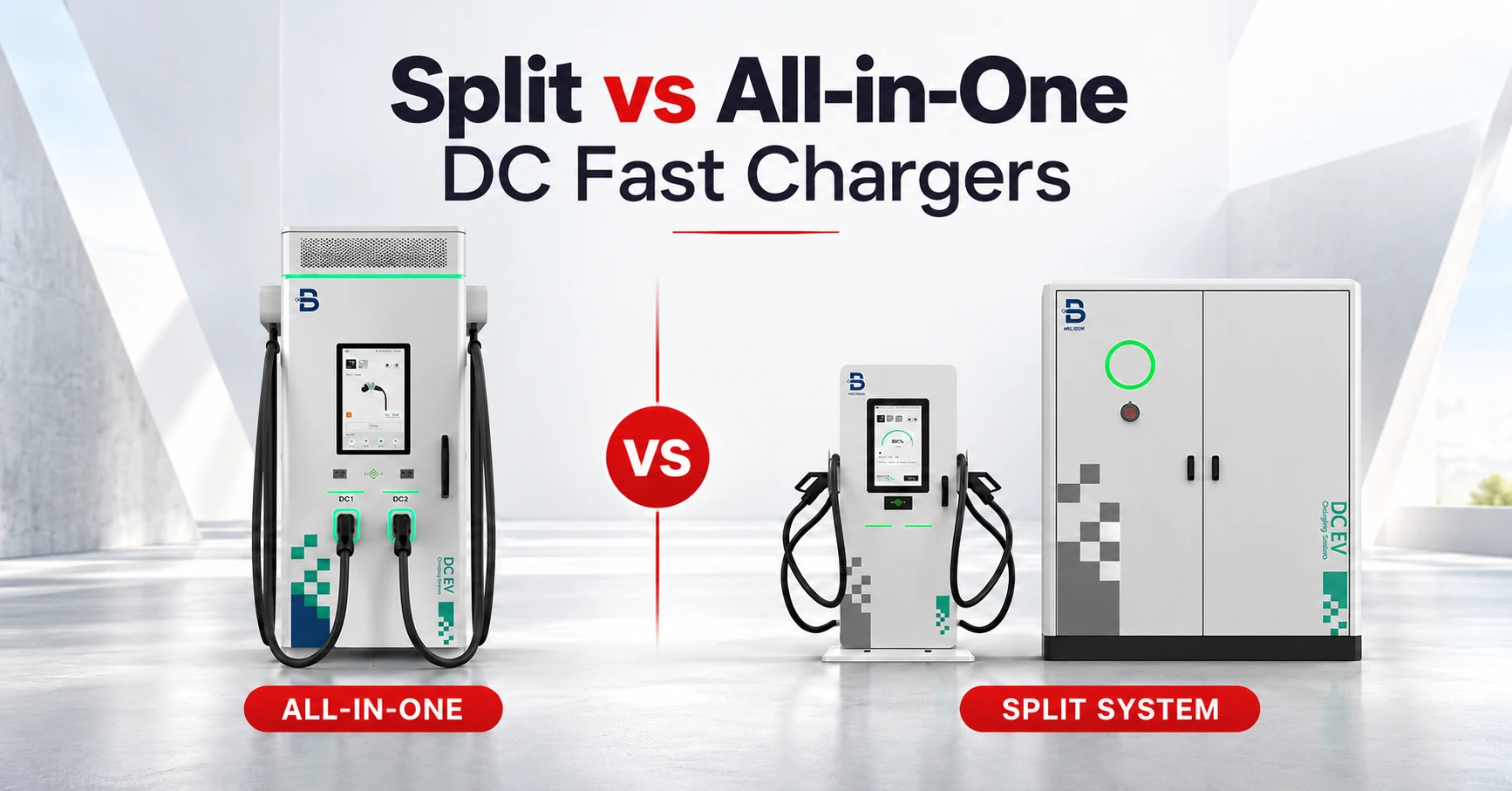
Both designs convert the site’s alternating current (AC) supply into direct current (DC) for vehicle charging. The main difference is where that conversion equipment sits: beside the driver in one cabinet, or away from the bays in a separate power unit.
Split vs All-in-One DC Charging: What Is the Difference?
All-in-One: the Main Equipment in One Cabinet
An all-in-one, or integrated, DC charger combines the main power-conversion equipment, controls and charging interface in one enclosure. Drivers connect their vehicles directly to that unit.
This can simplify a small installation because there is no separate power cabinet to position and connect to remote dispensers. It still needs an appropriate electrical supply, foundations, protection and space for safe use and servicing.
Split: a Power Cabinet and Separate Charging Dispensers
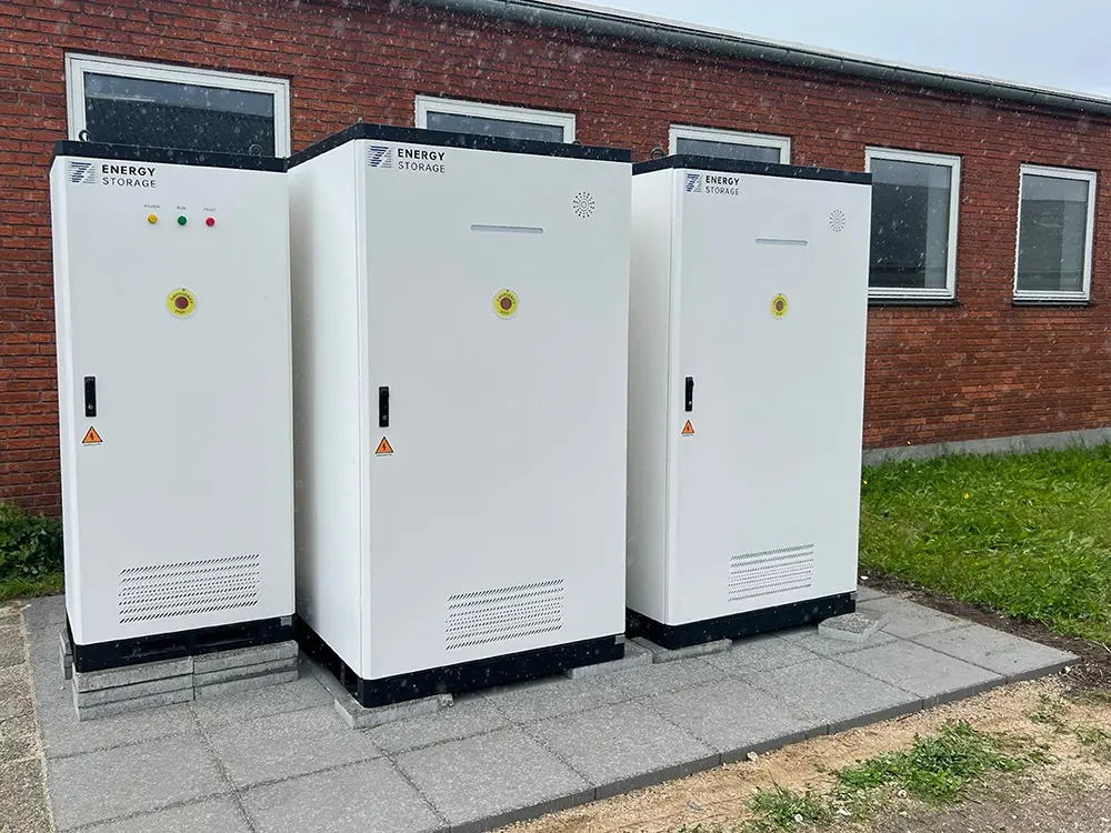
A split system places the main power-conversion equipment in a separate cabinet and sends DC power to dispensers beside the vehicles. A dispenser holds the charging cable and driver interface. Some suppliers describe similar layouts as distributed charging, but their power-routing and sharing arrangements can differ.
This arrangement gives you more freedom to position the driver-facing equipment. A suitable system can distribute its installed power across several charging outputs. However, the separate cabinet and the cable routes must also fit the site.
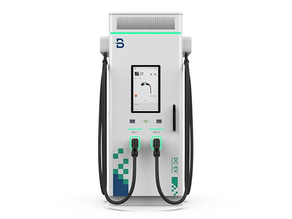

Power sharing and modular construction are not exclusive to split systems. Some all-in-one chargers support both. Compare the functions of the quoted models rather than assuming the enclosure tells you everything.
Split vs All-in-One DC Fast Chargers at a Glance
| Decision Factor | All-in-one | Split system |
|---|---|---|
| Equipment layout | Main power equipment and charging interface share one cabinet. | A separate power cabinet supplies dispensers at the bays. |
| Space | One equipment location per unit, with operating and service clearances. | Smaller dispensers can help bay layout; the power cabinet still needs its own space. |
| Power sharing | Available on suitable models, within their supported outputs. | A shared cabinet can serve several outputs, within its routing and power limits. |
| Installation | No separate cabinet-to-dispenser link; site electrical and civil work remain necessary. | Include cabinet-to-dispenser power and communication routes in the design and quotation. |
| Expansion | Add units or supported modules, with enough electrical capacity. | Add compatible outputs, modules or cabinets where the ordered system supports them. |
| Faults and servicing | A unit fault may affect its outputs; shared site equipment can affect more units. | A dispenser fault and a shared-cabinet fault can affect different numbers of bays. |
An all-in-one unit can suit a simple first phase. A split layout is worth comparing when shared power or flexible dispenser placement is useful.
Which Design Fits Your Charging Site?
A Small Retail Site Adding Its First Chargers
If a shop is adding two charging bays and has suitable electrical capacity nearby, start with an all-in-one proposal. Compare the equipment location, cable reach and installation cost. A split layout may still be useful if a separate service area makes the parking layout work better, but it should solve a real site problem.
A Public Hub with Several Busy Bays
A split proposal becomes worth assessing when several vehicles need different amounts of power at the same time. One vehicle may accept high power while another is near the end of its session. A compatible system can adjust each vehicle’s share as demand changes, within its total and per-output limits.
Request a drawing showing the power cabinet, each dispenser and the cable routes, together with the power available to each vehicle during the busiest period. More connected bays do not mean more total charging power.
A Fleet Depot with Fixed Departure Times
For a fleet, start with the energy each vehicle needs before it leaves. Several vehicles parked overnight may not need maximum power together. Vehicles returning shortly before their next shift may do.
A split system can suit distributed parking and shared power. Several integrated units may suit a phased rollout or separate operating areas. Compare both against the actual arrival and departure schedule, including what happens if equipment is unavailable.
These are planning examples, not measured BENY customer results. If you are still deciding between AC and DC charging, see the commercial AC vs DC charging guide first.
Four Power Limits to Keep Separate
A charging proposal can contain several different kW figures. Keep these limits separate:
- Total Charger/Cabinet DC Output: the DC power available to share across the connected outputs.
- Terminal and Cable Limits: how much an individual connection can deliver at the vehicle’s voltage and within its current and temperature limits.
- Available Site Supply for Charging: the electrical input capacity available after other loads and within the site’s agreed supply limit.
- Vehicle Acceptance: the power the vehicle can take. Battery temperature and state of charge can change this during a session.
Available site supply is not simply the transformer’s nameplate rating. Other loads, switchgear and supply cables can also limit the capacity available for charging.
A simple power-budget example: a system with 600 kW of total DC output has enough power for four 150 kW allocations in theory: 4 × 150 = 600 kW.
That arithmetic is not a charging guarantee. The equipment must support the allocation, the site must supply enough input power including losses, and each vehicle must be able to accept it. Adding two more cables would not increase the 600 kW total.
A 500 kW terminal on a 720 kW shared system does not mean every terminal can supply 500 kW simultaneously. Ask for the output available when one, two and several vehicles are connected. This is more useful than comparing the largest number on each brochure.
Shared vs Dedicated Charging Power
A dedicated power allocation keeps a specified portion of installed power assigned to an output. Where supported, dynamic power allocation lets controls redistribute available power as vehicle demand changes; it need not be an equal split. Confirm the sharing rules for the quoted model. Sharing does not increase the cabinet’s total rating.
Site load management is a separate function: it limits the combined power drawn by charging equipment to keep the site within its electrical limit. Both integrated and split chargers can be used with suitable load management. A proposal should explain both how the outputs share power and how the whole site stays within its supply limit.
Compare the Whole Installation, Not Just the Cabinet
Layout and Cable Routes
A slim dispenser can leave more room beside a vehicle, but a split system still needs space for its power cabinet, ventilation and maintenance access.
The quotation should include DC and communication cables between the cabinet and dispensers, plus any required ducts, trenching, foundations and pavement reinstatement. Confirm whether the route uses existing ducts, cable trays or new trenches before comparing equipment prices.
Check how drivers park, where their charging ports are, and whether cables reach without crossing walkways. Vehicle protection and accessible routes belong on the same drawing. The charging station layout guide covers the wider site-planning questions.
Noise near Drivers and Neighbours
Moving a split system’s main power cabinet away from parking bays can move a major noise source away from drivers. Check its position relative to nearby offices and homes as well. Compare noise figures for the exact cabinet and dispensers at the same stated distance and load.
Cooling and Hot-Weather Output
Cable cooling: liquid cooling removes heat from the charging cable and connector to support high-current charging. Confirm the current rating, weight and handling of the quoted cable assembly.
Power module cooling: check the cabinet’s own specification. Liquid-cooled cables do not mean that the power modules use a liquid-cooling loop. BENY’s BSDC720 datasheet lists an optional liquid-cooled CCS2 output up to 500 A and forced-air cabinet cooling with an independent duct. Confirm the ordered configuration.
Thermal derating curve: this shows how available output changes as temperature rises. Derating means reducing output to stay within equipment limits. A maximum operating temperature does not guarantee full output at that temperature.
Check the Documents for Your Country
Before ordering, ask for compliance documents for the exact model and installation country. IEC 61851-23 covers DC charging equipment. For U.S. projects, have the installer check the locally adopted electrical code, including NEC Article 625, and the local permit and inspection requirements.
For CE-marked equipment, request the EU Declaration of Conformity. Check that any required product listing covers the quoted model and system configuration. Choosing a split or all-in-one layout does not replace these checks.
Maintenance and Availability
A single point of failure (SPOF) is a component whose failure alone can stop the system being assessed. Ask the supplier to identify the affected outputs after a dispenser, power-module, shared-controller or common DC-bus fault. A dispenser may serve more than one connector, and one power cabinet may serve only part of a larger site.
For each fault, confirm how many outputs remain usable, how much charging power remains and how the failed section is isolated. Several separate all-in-one units can limit a single unit’s impact, but shared electrical supplies or controls still need assessment. Check the replacement time for the affected part.
Modular construction alone does not prove redundancy. If a supplier offers N+1 redundancy, ask it to show how the required charging load is maintained with one module unavailable.
Neither architecture guarantees uninterrupted charging. Agree the service response, spare parts, warranty responsibilities and safe isolation procedure. The U.S. Department of Energy’s charging infrastructure maintenance guidance also recommends defining maintenance responsibilities and response times.
Future Expansion and Total Cost
Separate three expansion goals: more places to plug in, more simultaneous output, and higher power for one vehicle. They can require different hardware. Spare dispenser connections alone do not create extra power.
Before a power upgrade, confirm compatible power modules, usable slots and the cabinet’s supported output and cooling capacity. Separately, check the site’s transformer loading, agreed supply limit, switchgear and cables after allowing for other loads.
Compare quotations for the same required service: the same active bays, vehicle needs and expansion phase. Include equipment, electrical upgrades, foundations, cable routes, controls, commissioning and ongoing support. A cheaper cabinet can become a more expensive installation if its layout does not suit the site.
BENY Options to Compare
BENY offers both arrangements. The following examples show why the model details matter as much as the architecture.
BDCC: an Integrated Option for Commercial Charging
The BENY BDCC dual-connector series covers rated powers from 120 to 480 kW and has two CCS2 connections. BENY describes a modular design. The quoted power is the whole charger’s rating, not that amount guaranteed at each cable.
Use this option to assess a self-contained installation. Have the offer identify the exact power model and the output-sharing arrangement when both vehicles charge.
BSDC720: a Separate Cabinet and Charging Terminals
The BENY BSDC720 split DC system separates its power cabinet from the terminals. Its published specifications describe up to 720 kW of system power and a terminal maximum of 500 kW.
The linked datasheet describes configurations with up to nine charging outputs. The actual terminal mix and available simultaneous power must match the ordered configuration. Nine outputs do not mean nine vehicles can each charge at 500 kW.
A Real Layout Example: a German Car-Wash Site
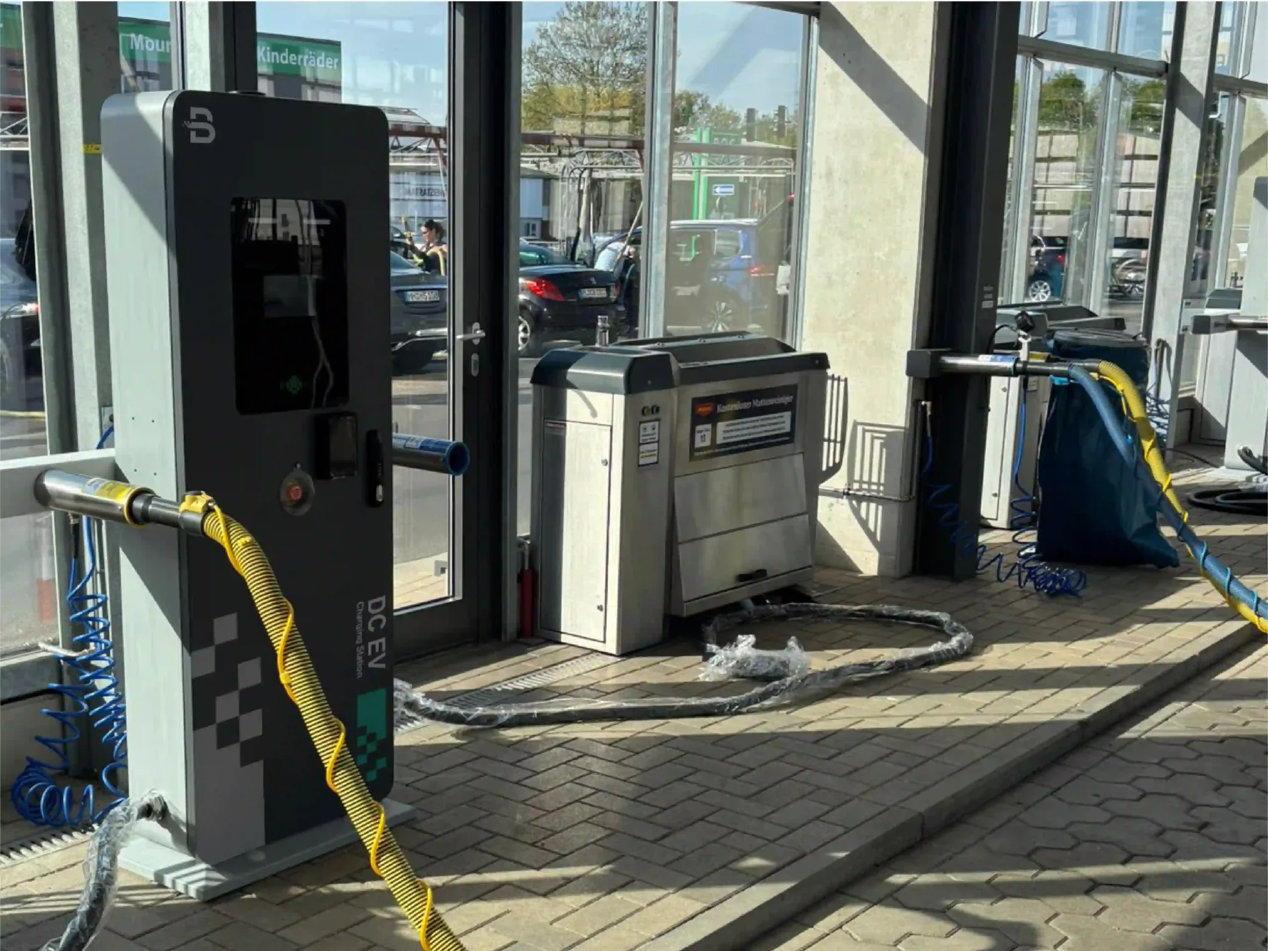
BENY’s German car-wash charging project uses a split arrangement with separate charging terminals. The project photographs show narrow terminals positioned within the service area, illustrating how charging access can fit around an existing business layout.
Ask BENY to Compare Both Layouts for Your Site
Send your country, site drawing, available electrical capacity, vehicle types, expected parking time and first-phase bay count. Include the number of bays planned later.
Ask for the equipment locations, simultaneous output and complete installation scope for each suitable option.
Explore BENY Commercial EV ChargersFAQs
Is a Split DC Charger Faster than an All-in-One Charger?
Not automatically. Compare the power each vehicle can receive when the required bays are in use. Charger output, cable current, vehicle voltage, battery temperature and state of charge can all limit the result.
Can an All-in-One Charger Share Power?
Yes, suitable models can share power between supported outputs. Check the exact model rather than treating power sharing as a split-only feature.
Is Distributed Charging the Same as Split Charging?
Sometimes. Suppliers may use distributed charging for a split layout, but the terms do not guarantee the same power-routing or sharing arrangement. Check where the conversion equipment sits and how its outputs are supplied.
Are Modular DC Chargers Always Split Systems?
No. Modular describes equipment built from power modules; split describes where the conversion equipment is located. Integrated chargers can also use modules for servicing or supported power upgrades.
Is a Dual-Port DC Charger the Same as a Split Charger?
No. Dual-port means the unit has two charging connections; split describes a separate power cabinet and terminals. Ask whether both ports work simultaneously and how they share power. Two cables do not automatically double total output.
Does a Split System Use Less Space?
It can use less space beside each vehicle because the dispenser is separate from the main power equipment. Compare the total site layout, including the power cabinet, service clearances and cable routes.
Which Design Is Cheaper?
An all-in-one layout avoids separate cabinet-to-dispenser DC cable runs, which can simplify installation at a small site. A split layout can share installed power across several bays, but adds separate equipment and cable routes. Compare complete installation quotations, including any required trenching and pavement reinstatement, for the same simultaneous output and expansion plan. Neither design is always cheaper.
Can I Add Dispensers without Increasing the Power Supply?
Extra dispensers add connection points, not power. The system must support the added outputs. To increase simultaneous output, confirm compatible modules and slots, the cabinet’s limits and available site supply, including the transformer and distribution equipment.
Is a Split Charger Quieter at the Bay?
It can be, because the main power equipment can be placed away from the driver. Compare noise data for the specific dispenser and cabinet, and check where the cabinet sits relative to neighbouring buildings.
Does a Split Charger Handle Hot Weather Better?
Not automatically. Layout and cooling are different choices. Compare the quoted models’ thermal derating curves, including cable limits. A stated operating temperature range does not guarantee full power throughout that range.
References
- BENY BDCC dual-connector DC charger: product information and linked datasheet.
- BENY 720 kW split DC charger: product information and linked datasheet.
- BENY: split DC charging at a German car-wash site.
- U.S. Department of Energy, Alternative Fuels Data Center: Operation and Maintenance for Electric Vehicle Charging Infrastructure.
- IEC 61851-23:2023: DC electric vehicle supply equipment — public scope summary.
- U.S. Department of Energy, Alternative Fuels Data Center: Procurement and Installation for Electric Vehicle Charging Infrastructure.
- DOE Building America Solution Center: NEC Article 625 overview in its home-charging guide.
- European Commission: CE marking and the manufacturer’s EU Declaration of Conformity.
Product, project and maintenance sources accessed 27 October 2026; compliance sources checked 29 October 2026. Product ratings describe particular equipment and configurations. The project proposal should identify the current model, output allocation and installation requirements.