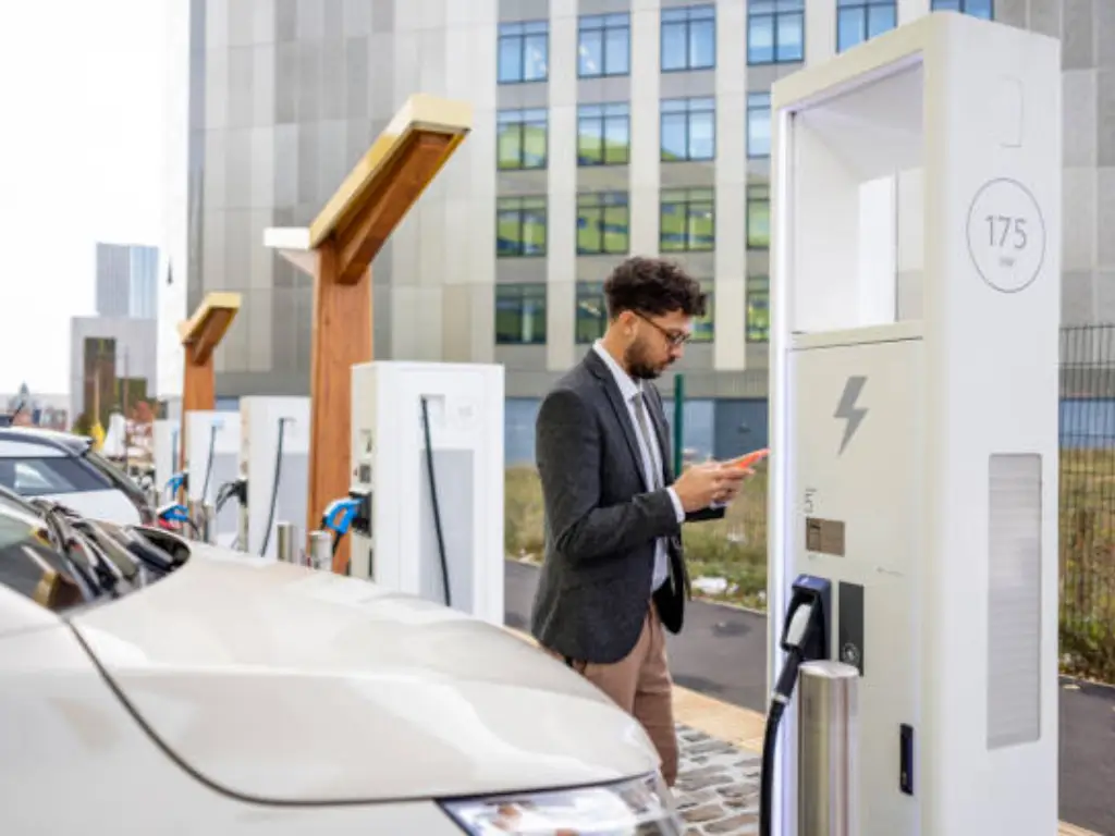
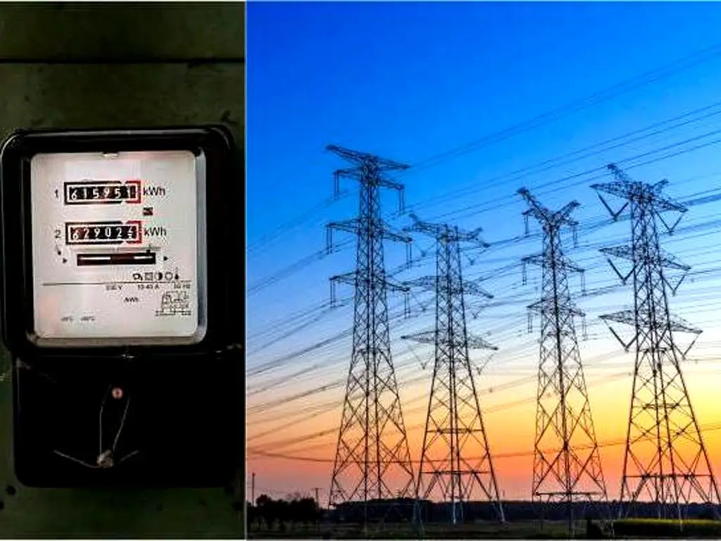
A Commercial and Industrial (C&I) solar PV project is the construction of a power plant on-site that directly transforms sunlight into electricity to power your business. The significance of it is simple: it gives you direct control over your energy future. You can create your own clean power, which is a potent instrument to control unpredictable electricity prices, achieve sustainability objectives, and provide stability in operations, transforming a fluctuating cost into a long-term, predictable asset.

A C&I solar system is not merely an environmental statement; it is a high-performance financial resource that provides real returns by solving major business issues. The main strategic strengths are:
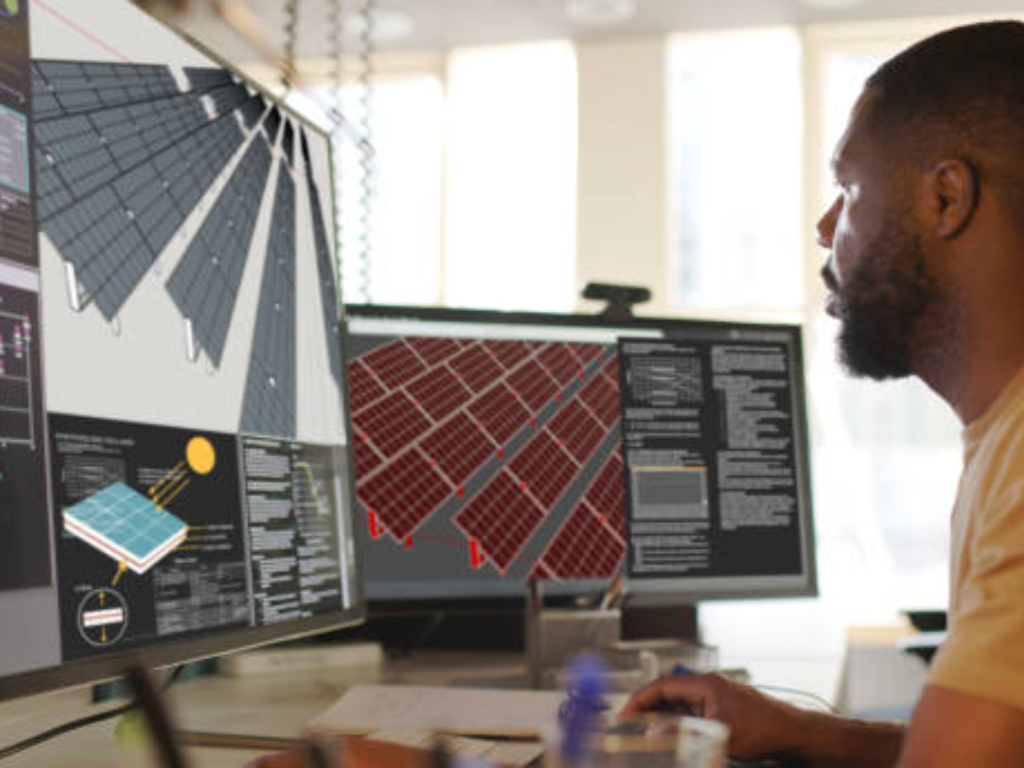
A commercial solar PV system is an integrated assembly of highly engineered components working in concert. Understanding the function of each core component is essential for appreciating the design process and making informed procurement decisions.
The most visible element of the solar system is the solar panel, or the PV module. The panels are made up of an array of solar cells, usually silicon-based, which carry out the photovoltaic effect, which is the conversion of photons in sunlight to direct current (DC) electricity. High-efficiency monocrystalline or polycrystalline panels are a common application in the C&I industry to make the most out of the available rooftop or ground space. The choice of the solar module is a very important initial step that determines the total power output and the physical area of the solar installation.
The solar power plant is made up of inverters. Their important role is to transform the DC electricity generated by the solar panels into alternating current (AC) electricity. Commercial buildings and the utility grid use the standard form of power, which is AC power. In commercial solar applications, various inverter types can be used, such as large central inverters to serve the whole system, or a number of string inverters to serve power on various parts of the solar array. The inverter technology selected has a direct effect on the efficiency of the system, flexibility in design, and maintenance procedures.
| Criteria | Large Central Inverters | Traditional String Inverters | String Inverters + Optimizers |
|---|---|---|---|
| Initial Cost | Lowest on a $/watt basis for large, uniform sites (>1MW). | Low to Medium. Cost-effective for a wide range of C&I projects. | Highest. Optimizers add a per-module cost to the system. |
| O&M Complexity | Low (fewer units). However, a single failure results in 100% system downtime. | Medium. A single failure only impacts one section of the total solar array. | Higher. More electronic components on the roof to monitor and service. |
| Shading Mitigation | Very Poor. The performance of a massive array section is limited by the single worst-performing panel. | Poor. The performance of an entire string is limited by its lowest-producing (e.g., shaded) panel. | Excellent. Each panel produces its maximum power independently of others. |
| Design Flexibility | Low. Requires large, identical blocks of panels in the same orientation and tilt. | Medium. Allows for multiple arrays, but each string must have a uniform orientation. | Excellent. Enables designs across multiple roof planes, orientations, and tilts, even within the same string. |
| Module-Level Monitoring | No. Only provides system-level or inverter-level data. | No. Only provides string-level or inverter-level data. | Yes. Provides granular data on the health and performance of every individual module. |
| Safety | Standard. Module-level rapid shutdown is more complex to implement. | Standard. Can be paired with certified string-level rapid shutdown devices. | Highest. Natively provides module-level rapid shutdown, the safest solution for first responders. |
The choice of inverter should be a direct response to the project’s specific needs. Use the following framework to guide your design decision:
The racking and mounting system is the structural base that holds the solar panels to the roof of a building or the ground. This is a designed structure that is essential to the stability and sustainability of the whole solar energy system. In the case of rooftop installations, there are attached mounts that penetrate the roof and ballasted mounts that hold the array in place without penetrations. In the case of ground-mounted systems, one can have fixed-tilt systems or tracking systems that track the direction of the sun. The mounting system should be such that it can support the local wind, snow and seismic loads throughout the entire life of the project.
This group includes the fundamental electrical equipment that safely conducts, unites, and safeguards the passage of power within the system. It consists of wiring, fuses, and combiner boxes, which combine the output of several strings of panels. Importantly, it also incorporates circuit breakers and disconnect switches that offer overcurrent protection and a way of de-energizing the system safely to allow maintenance. These are the main parts of the system that make the PV system the central nervous system, which guarantees the reliability and safety of power flowing between the panels and the point of use.
The current commercial solar systems have advanced monitoring and control systems. These systems offer real-time information on energy generation, performance of the components and the health of the system. Facility operators and system operators are able to monitor the important metrics, get automatic notifications about possible issues, and create reports to check performance and financial gains. This intelligence layer is essential to proactive maintenance, which will guarantee the system is running at its optimum efficiency and will provide the anticipated energy savings throughout its life.
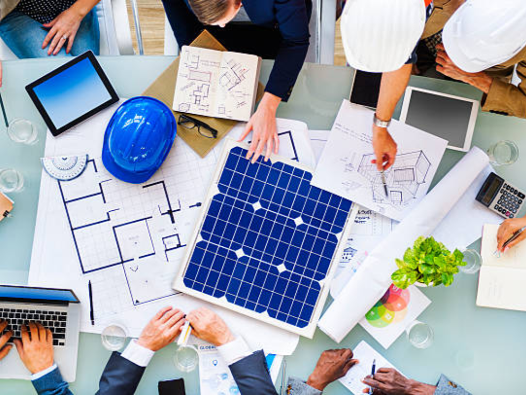
An effective C&I solar project is a planned effort that takes an idea to an operating asset in a sequence of specific steps. This lifecycle strategy aims at reducing risk, ensuring quality assurance, and giving all stakeholders clear points of decision. To get through the intricacies of solar development and design, it is important to understand how this process works, starting with feasibility and going on to operation.
This is the first step, the analytical basis of the project, which is to provide an answer to the key question: Is this a technically feasible and financially viable investment? It is a cheap, high-value step that gives the information required to make an informed go/no-go decision prior to investing a lot of capital.
Major Measures towards a Comprehensive Evaluation:
After establishing the feasibility of a project, the next step is to establish the optimal financial size of a project. The main idea here is fundamental: the aim is to maximize the return on investment (ROI), rather than the installed capacity. In areas where the net metering or energy export policy is poor, a situation of diminishing returns can be experienced, whereby the larger the system, the less the revenue. As such, the size of the system should be made in such a way that it creates the ideal balance between energy generation, the local utility rate structure, and the project-specific financial goals.
The design process should start with a clear business goal. To begin with, the main purpose of the installation should be identified:
Professional designers use marginal benefit analysis to determine the sweet spot that will maximize the IRR. This is done by modeling the financial returns of the project at different capacity increments. The IRR and NPV of each possible system size can be calculated, allowing the designers to identify the point of diminishing returns, the size of the system at which additional panels will start to pull the overall rate of return of the project down. As an example, a roof of a factory can host a 1 MW system. Nevertheless, it could be analyzed that the IRR of the project is maximized at 15 percent with a 750 kW system because of low weekend energy consumption and a low export rate. The size increased to 1 MW, and the overall energy produced, might result in a decrease in the IRR to 13.5% since a significant part of the energy is sold to the grid at an extremely low price. The size that is most economical in this case is 750 kW.
Other important factors that need to be included in the design before the finalization of the capacity are:
It is important to mention that the quality of all these optimization studies relies entirely on the quality of the data collected during Phase 1, that is, at least 12 months of 15-minute interval load data and the appropriate utility rate tariffs. Any advanced financial model is just a house of cards without a sound database.
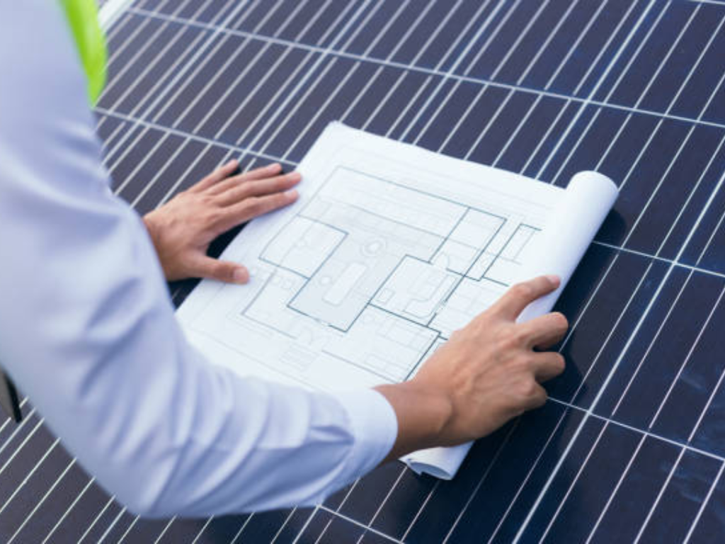
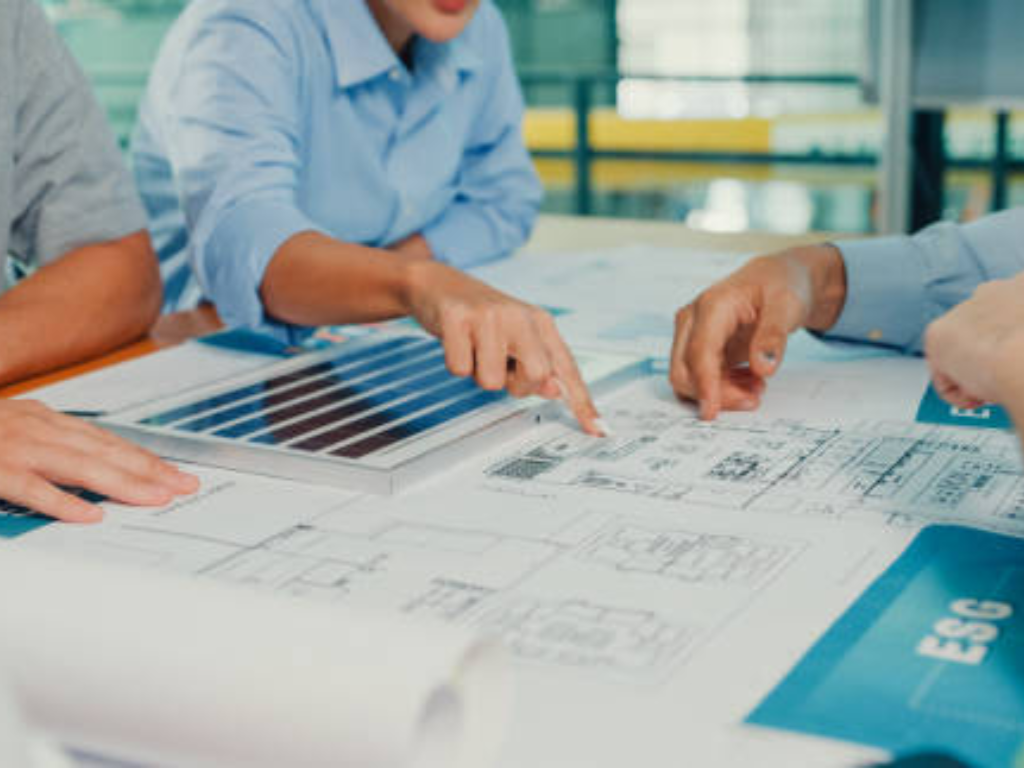
It is the stage during which the project moves out of the concept and into a detailed, constructible set of construction documents. The most critical element in the timely completion of a project within budget and to the best standards of quality and safety is a professional and exhaustive design.
The project enters the physical construction and grid integration phase with a completed design. Here, the emphasis is on quality control and the formal process of making the system online.
While solar panels and inverters are the primary engines of energy production, the safety, longevity, and operational uptime of your commercial solar asset depend entirely on its electrical safety components. These devices—circuit breakers, disconnects, and rapid shutdown units—are not passive accessories; they are active protection systems. Understanding what they do, when you need them, and how to select them is fundamental to mitigating risk and protecting your long-term investment.
A commercial solar array is a high-voltage DC power plant that runs on your property. To handle this power safely and to guarantee the system has a long life, a set of important safety elements is needed. They have different and essential protective purposes.
These components may be installed separately in a small residential system. Nevertheless, dozens of parallel strings of solar panels are common in commercial and industrial (C&I) projects. It would be complicated, expensive and would introduce many possible failure points to manage the wiring and offer individual protection to each string.
This is why C&I systems nearly universally use a Combiner Box. A combiner box, as the name implies, is an electrical housing that is intended to safely combine the output of several solar strings into one larger main cable.
More importantly, the combiner box is also the central housing where the most important safety components are combined. A standard commercial combiner box will include:
A combiner box simplifies the wiring process by incorporating these devices into a single, strong, factory-assembled unit, increases safety, and concentrates the protective functions of the system. In choosing a solution, it would be the industry practice to source a pre-wired and certified combiner box from a manufacturer such as BENY. This method will ensure that all internal parts are rated and installed to the utmost standards, which will save a lot of labor on-site and also eradicate the frequent mistakes that can occur during wiring, which may jeopardize the safety and performance of the system.
Rapid Shutdown is a compulsory safety need in most areas, such as those that adhere to the U.S. National Electrical Code (NEC). It is designed to give a means of de-energizing the solar panels on the roof within a short period of time to shield first responders against the risk of shock during an emergency.
How you achieve this depends entirely on your choice of inverter technology.
How to Select: The selection of the add-on RSD unit is important in this case. The most important selection criteria are:
Objective verification is essential for a long-term commercial solar asset. True quality is validated through independent testing and certifications from internationally recognized authorities. Understanding these standards allows you to accurately assess the safety and reliability of the components selected for your project.
This section outlines two frameworks used by industry experts to evaluate component quality, covering mandatory requirements and indicators of long-term performance.
Safety certifications are the baseline requirement for any component used in a solar project. They confirm that a product has passed rigorous testing for electrical safety and its ability to withstand specific environmental conditions. These certifications are non-negotiable for legal installation and ensuring project safety.
Key standards to verify for major components include:
A manufacturer’s commitment to securing a broad range of global certifications is a strong indicator of robust quality control. For example, when a company like BENY holds certifications from UL, TÜV, CE, and SAA, it demonstrates that its products meet the highest safety benchmarks in multiple demanding international markets.
Beyond mandatory safety standards, independent reliability tests predict a component’s long-term durability and performance. These tests subject products to conditions far more severe than standard certification protocols to simulate decades of real-world operation.
For solar panels, the most respected benchmark is the PV Evolution Labs (PVEL) PV Module Reliability Scorecard.
Top-tier electrical component manufacturers apply similar principles through extensive in-house testing, such as salt spray and IP (Ingress Protection) assessments, to validate product endurance in diverse and challenging environments.
The commissioning of a solar PV system marks the beginning, not the end, of its operational life. To ensure the system consistently delivers its projected energy production and financial returns, a proactive Operations & Maintenance (O&M) strategy is essential. A robust O&M plan protects the asset’s value and maximizes its performance over time.
O&M activities are typically divided into two categories. Preventative maintenance includes scheduled tasks such as cleaning solar panels to remove dirt and debris that can reduce energy output, inspecting electrical connections for tightness and corrosion, and verifying that inverters and monitoring systems are functioning correctly. Corrective maintenance involves responding to system faults or failures. With a comprehensive monitoring system in place, many potential problems can be identified and addressed before they lead to significant downtime. Neglecting O&M can lead to a gradual degradation in performance, eroding the cost savings and ROI that justified the initial investment.
A successful Commercial & Industrial solar project is the direct result of meticulous planning, expert engineering, and an uncompromising commitment to quality. As a long-term asset designed to perform for over 25 years, its success is ultimately determined by the reliability of every component—especially the critical safety and distribution gear that protects your entire investment.
To build your solar future with confidence, prioritize partners and component manufacturers with proven experience and a portfolio of globally certified products. By ensuring your system is built with high-quality, durable components from the start, you secure decades of predictable, clean, and profitable energy.
© 2025 C&I Solar Project Guide – Professional Solar Solutions